


We are moving all Atari Lynx related content over to Atari Lynx Vault and all our shop content over to K-Retro Gaming. Please update your bookmarks!
As a result of this change, the following will no longer be available: Online Lynx Emulator, Collection Tracker, Game Ratings, News. If you are interested in contributing content to Atari Lynx Vault, we are seeking editors and maintainers.
Why is this happening? First - the Atari Gamer branding is changing to K-Retro Gaming to allow us to expand to providing games, replacement parts, and mod services to other game consoles. And second - The content management system running Atari Gamer is out of date and Google AppEngine (where the website runs) will no longer allow it to run after the 30th January 2024, so in order to preserve all content we switched to a new and modern content management system and chose a website domain that better suits the subject matter. Since we are operating this website in our spare time, on top of full time family and job committments, some features had to be dropped.
It's easy to forget that Atari Lynx is 30 years old this year and unfortunately that means a typical Lynx will start having electronic components fail. Jon who regularly writes game reviews and articles for Atari Gamer has sent his ageing Lynx to Atari Gamer for repair and we gave it a full make over! 😎
Jon's Lynx had a couple of issues - speaker volume was a little low, it would not power on after extended use and the screen had pixel rot. All of these were addressed by recapping the motherboard, replacing the power circuit and installing a LCD screen and VGA out port. So lets see what we did in more detail...


First the battery cover had to be removed, it was a little stuck in place so a spudger was used to help to pry open the compartment without damaging those plastic clips that hold the cover in place. With the batteries removed the Lynx was laid front face down ready for disassembly (don't worry a soft towel was used to prevent scratches).
To disassemble a Lynx, its rubber feet need to be removed. These are held in really well with glue but it's nothing that a metal spatula won't help lift. There are four screws, two under each rubber foot. Then there's an additional screw inside the battery compartment. There are also small clips all around the inside of the Lynx shell but generally these just pop off once a the screws are removed and a little pressure is applied to each side of the shell.

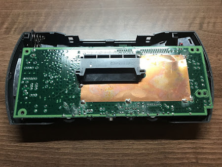 Re-Capping the Motherboard
The motherboard has a couple of cables connected to it. There are the two ribbon cables using ZIF sockets, two-pin speaker connector and a 3-pin screen backlight connector. The ZIF sockets have little notches that need to be pulled straight up relative to the socket, which releases those ribbon cables. The other two connectors pull out with little force.
When removing capacitors it's important to have two things - a good desoldering iron and a map of all capacitor locations. Console5 has a good resource page with all capacitor locations here.


Most of the capacitors are no trouble, but the C3 capacitor sits inside the RF shield and has a copper sheet covering its contacts on the opposite side. This requires some solder wick to peel back the copper sheet, then the capacitor legs can be accessed and desoldered. The desoldering iron doesn't fit here so more wick is required to remove this capacitor.


With all the old capacitors removed, all the new ones can be fitted. Since this repair job included installation of a LCD screen, the C32 and C33 capacitors were not included in the capacitor replacement kit, but we installed some replacements anyway. Installation of the rest of the capacitors was a simple procedure - making sure the values are correct, getting the +/- pins the right way around (negative is marked with a stripe) and soldering it in place.

Power Circuit Replacement
The MOSFET and Zenner diodes can fail on a Lynx, which can burn out the motherboard, so we replaced the whole power circuit. Before doing that however, since the LCD screen was being installed the old high voltage power circuit was first removed (L17, T1, Q14, Q13, C56, C55, VR1). Then the Q12 MOSFET, D13 Zenner Diode and Q7 and Q8 voltage regulators were desoldered. These later components were all surface mount so a solder wick was used to soak up most of the solder, then a scalpel was used to lift each of the legs while solder was still molten.


Once the replacements power components (from Console5) were fitted, the all-important voltage test was performed and we had ~5V power! Perfect, time to move on!

LCD Kit Wiring
At the moment there is only one option for a LCD kit (but that may change soon) and that's the McWill LCD/VGA mod for Atari Lynx. That's exactly what was installed into this Lynx. The VGA connector was first to be wired up. Nothing magical here but it's worth mentioning that pins 6, 7 and 8 were soldered together using cut off pins from capacitors installed earlier and then one wire connected from that trio to the LCD board.

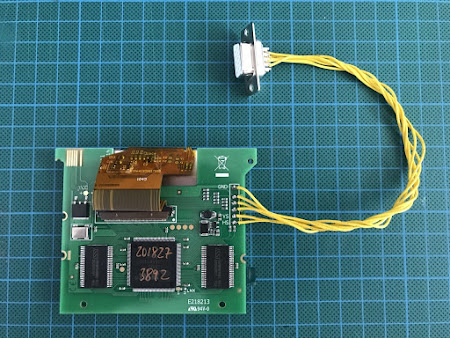
The rest of the wiring for the LCD board followed. Pin 2 on the U11 chip is hard to solder to but there is a trace coming off of it to a via, which can have a thin wire soldered into it as an anchor point. The backlight wire is then soldered to that point.


All wired up and the test run was successful!

 LCD Fitting
Before fitting the LCD, the old screen had to be removed. There are four screws that hold it in place. These screws are reused for securing the new LCD.


Something that always seems to come up with the LCD replacement is when it's fitted there is a metal strip on the left hand side which is clearly visible when playing the Lynx. The solution to that...black electrical tape to cover it up!


The extra bit of work cleaning out all of the dust and covering the edges is really worth it!

VGA Port Installation
First a quick test to make sure that the VGA output is working correctly...

The VGA port is not often put into a very convenient/out of the way location when this mod is done. The best place for it is of course on the rear of the unit and it fits perfectly there. Using the VGA connector as a template an outline was marked out and then a rotary tool made quick work of the plastic.


After securing the VGA port, all of the exposed terminals were covered up with electrical tape to prevent any possible short circuits and the Lynx was then put back together.

 The End
Now that's quite a mod job! Overall it took around 6 hours to complete, spread over two days. The end result was spectacular and Jon absolutely loved it when he received his Lynx back. If you're interested in getting your Lynx modded, get in contact and we'll see what we can do for you.
-AGIf your download doesn't start automatically after 10 seconds, please click here.